OK, I'll be honest, the amount of work I have done so far is very little
One project that I have had the time to get to is to make a strut brace for the car.
Being that funds are a bit tight, I didnt want to buy a brace, plus the fact that I have the machinery to make my own. Also, the majority of "off the shelf" strut braces do not work as well as they advertise. Reason being, many have heim joints or similar to make alignment of the brace easier. Being that this joint is "flexible", this allows some movement of the brace. The reason for the brace is to stop movement and keep the shock towers in the same position relative to each other at all times.
So...
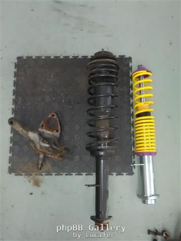
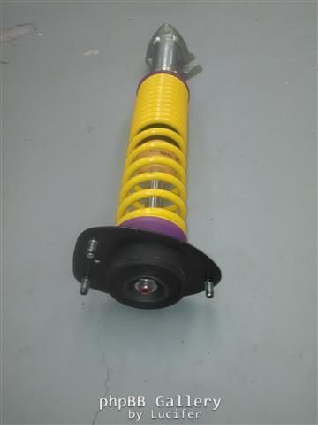
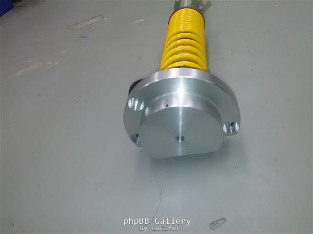
A while back I imported a set of Kerscher coil over shocks for the 1302. These are gems.
Here you can see one next to the standard shock which it is replacing.
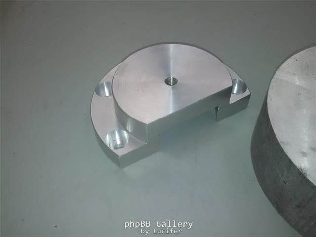
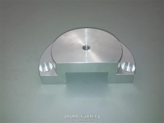
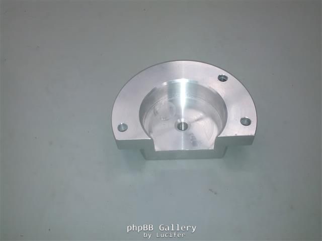
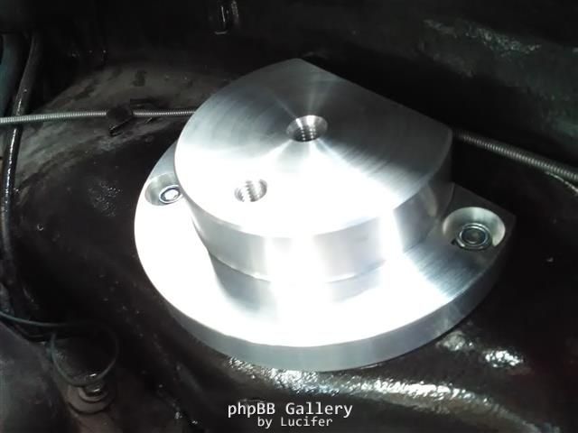
Below you can see the brace mounts which I made up. They are a bit overkill, but seeing as I am not using heim joints, I went through various options in my head os what will work and quite a few of them had to be given up on based upon the size of the material that I had at hand. At the end of the day, the design I chose to use is probably also the best design that I came up with and barely cost me a cent based on the fact that I used offcuts that I had lying around.
The mounts were made from 2 blocks of aluminium which I had leftover from another project.
Turned in the lathe to the size I wanted, then trimmed off in the mill. Also drilled for the mounting bolts and the brace mount.
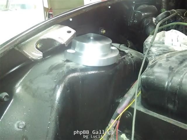
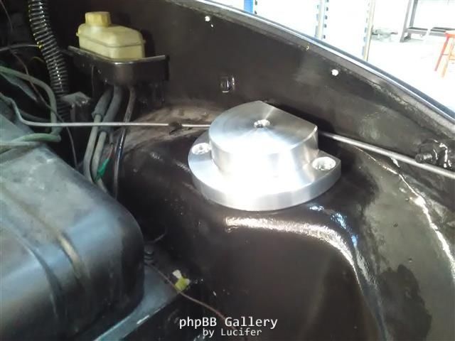
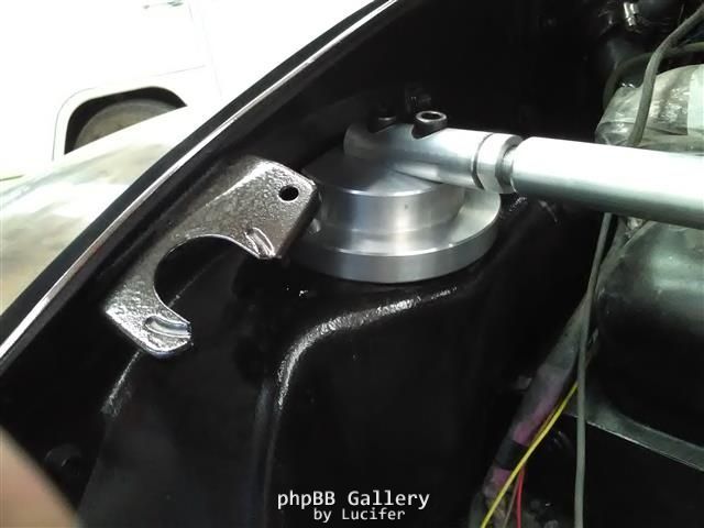
Here I have the new shock mount and bearing installed on the shock.
And the strut brace mount mocked up on it
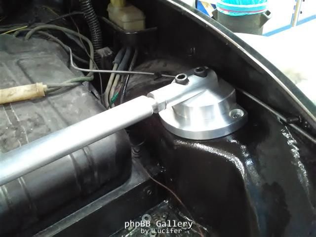
And now mocked up in the car
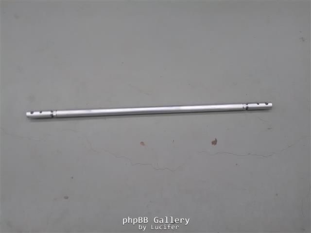
And now for the fun that drove me up the wall - making the bar.
I chose to use a leftover piece of 30mm solid aluminium bar. I cut two end pieces, which I machined to fit onto the mounts. I measured the angle that these end pieces need to be trimmed at to match the mounts, and this came to a nice 11.3deg. So I cut both to suit and drilled one mounting hole to begin the mockup. I also drilled a smaller hole for a second mounting bolt which I finished later.
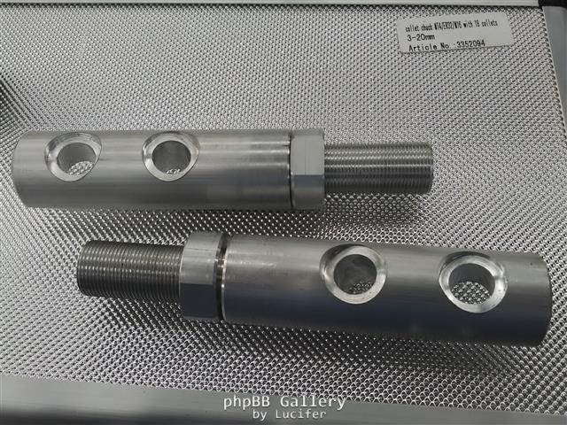
On these end pieces, to make the bar adjustable to properly fit the car, I threaded the ends. This little project drove me nuts.
I decided on a custom thread size of M20x1.25. Reason being that my internal threading bar can only thread up to a max pitch of 1.5mm.
There isnt exactly much tutorial on the internet on how to calculate the sizes that you need to work with and the info I found, might be mathematically correct, but didnt work for shiv when I cut my thread to those sizes... so after 3 days of threading and learning, I finally had a set of dimensions that I could work with and actually use.
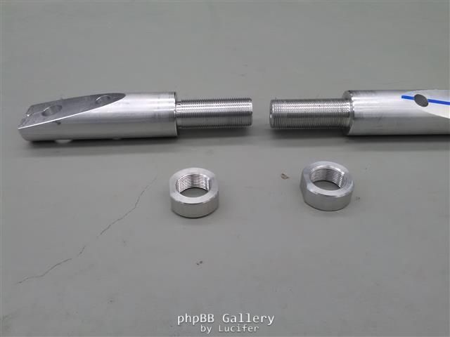
So now I could finish my end pieces and the tie rod itself.
And yes, one side is light hand thread, the other is left hand thread to allow on car adjustment.
I also made up two lock nuts and milled them for use with a 27mm spanner.
Then it came to mounting on the car and drilling and tapping my second bolt hole.
After all that was done and said, the entire project was bolted to the car.
The M8 shock mounting nuts torqued to spec and the M12 cap screws torqued to 80Nm. Also, being that the cap screws are mild steel and the mounts are aluminium, I used a LOT of grease to attempt to keep corrosion at bay (galvanic action).
And not to forget, the cap screws through holes also had to be milled at 11.3degress. OK, this was easy as after I cut the original mounting surface at 11.3deg, I just drilled the holes perpendicular to the surface.
Final pics
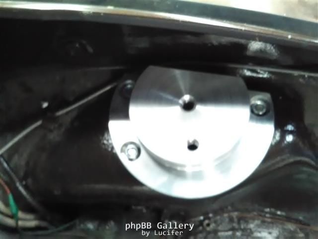
And yes, the whole system lines up perfectly.
Now I've got some more household projects that need attending to and hopefully I'll be able to get back into this 1302 soon