Ad blocker detected: Our website is made possible by displaying online advertisements to our visitors. Disable your ad blocker to continue using our website.
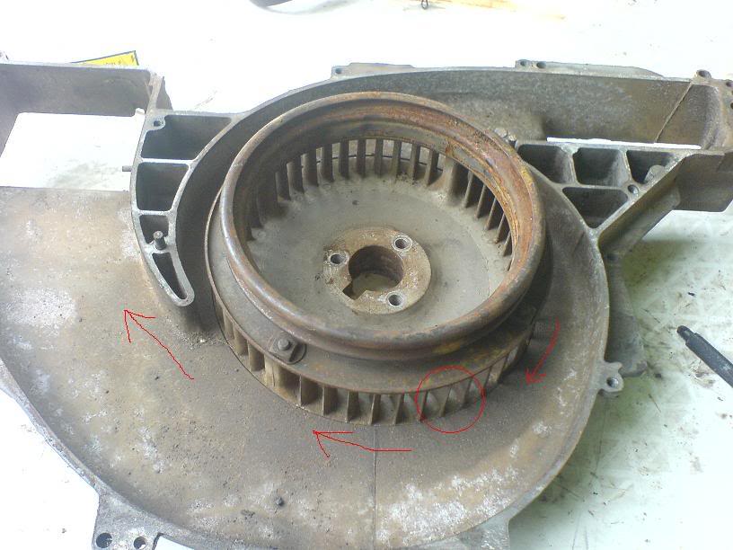
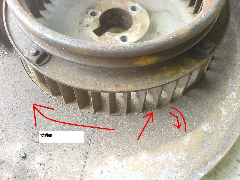
Here's something (amongst many) that I do not comprehend --- on the type 4 motor, fan rotation is surely clockwise, yet the fins on the fan is angled to then scoop the air. Looking at the fins on the fan surely they should be forcing the air to the sides and not scooping the air? Is this fan correctly assembled?
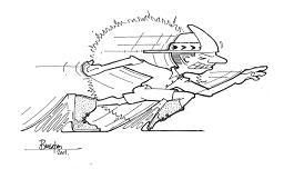
This is what I mean with scooping the air as it turns:
I do not understand this, can someone help and explain this to me?
Eben said: "ACVW's are made of logic."
Bugger said: "I am happy with the drum brakes when done right as this will be used rarely"
"If it can't be fixed with a hammer, you've got an electrical problem" said by someone.
I know jack about TYpe 4 engines, but look at the housing...that fan is blowing air outwards, through to the vents.
I'm presuming the shroud is similiar to a Type 1.
"Understeer is when you hit the wall with the front of the car, and oversteer, the rear. Hp is how fast you hit the wall, and Torque is how far you take the wall with you."
Look at the inside, it also scoops it from there. Centrifugal force sends it outwards. The reason for that angle is to help throwing the air outwards towards the exit
Tony Z wrote:Look at the inside, it also scoops it from there. Centrifugal force sends it outwards. The reason for that angle is to help throwing the air outwards towards the exit
And with all the covers and all the air is sucked in from the centre of the pully that has a plastic finger guard out wards
Adapterplates Available for Rotary in Beetle and others aswell
And Special Boxes built for Rotary Conversions and Scubies
Pierre
082 600 8663
CLick on Banner Below to be routed to the Web site
Believe it or not,the type 4 fan although turning only at crankshaft speed, has a bigger output at 800 litre per second than the faster spinning type 1 (600 litre per second,earlier pre-1971 540 litre per second).(Vw specifications found in various manuals).
The problem arises when the engine compartment seal is not in place,or even worse if any tinware is missing.Hot used air is then inhaled by the fan from the hot area below it the engine gets hotter an hotter as air just recirculates....
In 411-412 applications the inlet is connected with ducting to the air intakes,this ducting should also be in good condition.
Type 4 engines also had a heat shield,type of plate with asbestos in the middle,to reduce radiation from silencer to intake area.This was often discarded by layzy mechanics.
Thanks for that and for the figures Dawie. Very interesting. I also noticed that on the type 1 fan housing - the inside is very cleverly divided to prevent most of the hot air from the oil cooler to reach the heads. Instead the cool air flows over the top of the oil cooler to reach the heads and the hot air, after the oil cooler, is going down to the cylinders.
Very clever that. As those who read my post (project) will know - this cooling for the type 4 motor is still a huge headache for me.
I'm trying to understand the ins and outs of these fans to work out something cheaper for the upright cooling for the type 4 motor. Just found out that a new fan and housing for a Duetz Diesel aircooled motor is R6368.00 - WOW!! so that is out of the question.
How about a donation???
Eben said: "ACVW's are made of logic."
Bugger said: "I am happy with the drum brakes when done right as this will be used rarely"
"If it can't be fixed with a hammer, you've got an electrical problem" said by someone.
The Type 4 cooling system works very well if all the parts are there. Many people do convert them to a DTM upright system but this costs about as much as you stated. To do it inexpencivly you must keep the original cooling system.
Most fans work of of centrifugal force. the amount of air they flow is dependant on the length and width of the blades multiplied by the RPM. The longer the blade the higher the pressure. As you see your blades are very short to keep the pressure to a minimum. The VW motor does not operate at a constant speed so the blower wheel has to be designed tor the maximum efficiency at all speeds.
The fan blades are curved forward to reduce the ability of the fan to build pressure for efficiency reasons. if they were straight or curved backwards, the fan would build much higher pressure, deliver less air and use more HP. It also makes it less noisy.
It is a little difficult to explain without the math.
Good luck
Jim[/code]
And that is why I developed the impi setup as the others are just to expensive
Centrifugal fans work by using centrfugal force to sling the air outwards and you get forward and rearward facing vanes as Jim said some types just collect muck easier as well as stalling the air when running outside design parameters Wikipedia has a nice article with pictures.
Armand
Who cares how it's done in California?
(018) 473-0186
From what model Deutz is that? Plastic?The more common f6l912 series has an aluminium housing,the impeller behind it is also aluminium.
They allso made versions with less cylinders , the fan looks similar but the output is less,think the vanes are shaped differently for less output.
Think a lot of effort and time is needed by a capable guy to develop the right shroud,with the neccessary testing instruments.
Dawie wrote:From what model Deutz is that? Plastic?The more common f6l912 series has an aluminium housing,the impeller behind it is also aluminium.
They allso made versions with less cylinders , the fan looks similar but the output is less,think the vanes are shaped differently for less output.
Think a lot of effort and time is needed by a capable guy to develop the right shroud,with the neccessary testing instruments.
I was told that it was plastic...I have not yet seen the shroud in person
*scratches head in confusion*
The only reason that I was interested in it was because I could get it for free. When I go and pick it up, I will take some pictures...